1 什么是相机标定
影响相机成像过程的因素有很多。一束光先是从光源出发,落在物体表面。而后它又经过物体表面的反射,进入相机,穿过镜头和光圈,最后落在感光芯片上。这个过程中,物体的形状、方位、焦距、光圈数、感光芯片的大小、感光单元的分布间距……许许多多参数会对最终的成像产生影响。
相机标定是求解相机参数的过程。相机的参数又分为内参和外参。 内参包括相机的焦距、感光单元的间距、镜头畸变系数等。外参是相机相对于其它外部事物的位姿。一旦外参和内参是确定的,那我们就能确切地知道外部世界的某一个点发出的光线会落在图像的哪个位置。因此,许多任务,例如双目视觉、增强现实、立体匹配、单目3D目标检测……都需要使用准确的相机内外参。
内外参常常是无法直接精确测得的。我们无法直接用尺子测量镜头到感光芯片的距离,更无法用普通工具测量芯片上感光单元之间的间距(这是微米级别的尺寸),而镜头的畸变模型还带来更多更复杂的因素。要如何精确地得出这些数值呢?
首先,我们要建立相机的数学模型。 本文介绍常见的针孔相机模型。它用小孔成像来近似相机的成像过程。理解针孔相机模型,有助于学习其它相机模型,例如鱼眼相机模型和线阵相机模型。
相机模型建立后,我们用相机拍摄特定标定物,根据标定物的参数及成像效果,可以间接推断出相机的各项参数。
2 相机坐标系和世界坐标系

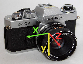
常见的相机坐标系如图 1所示。相机镜头朝前时,x轴朝右,y轴朝下,z轴朝前。
当然,你也可以采用不一样的坐标系设定。坐标系的定义不同不会影响相机模型和参数标定过程的数学本质,标定的方法也是一样的。但采取“另类”的设计有时会带来一些不必要的麻烦。
与相机坐标系相对的是世界坐标系。世界坐标系的定义根据问题的不同而不同。它可以定义在某张标定板上,也可以定义在某个传感器上。某点世界坐标系与相机坐标系上的坐标可以通过刚性变换来转换。假设\(\mathbf p_w\)是世界坐标系下的坐标,\(\mathbf p_c\)是相机坐标系下的坐标,那么存在选择矩阵\(\mathbf R\)和平移向量\(\mathbf t\)使得 \[ \mathbf p_c= \mathbf R\mathbf p_w + \mathbf t \]
这里的向量\(\mathbf t=(t_x, t_y, t_z)^T\)。旋转矩阵\(\mathbf R\)是三行三列的方阵。
解释一下旋转矩阵的计算。假设旋转的过程是绕著z轴旋转角度\(\gamma\),再绕y轴旋转角度\(\beta\),再绕x轴旋转角度\(\alpha\),那么旋转矩阵 \[ \mathbf R(\alpha, \beta, \gamma) = \left(\begin{array}{ccc} 1 & 0 & 0 \\ 0 & \cos \alpha & -\sin \alpha \\ 0 & \sin \alpha & \cos \alpha \end{array}\right) \left(\begin{array}{ccc} \cos \beta & 0 & \sin \beta \\ 0 & 1 & 0 \\ -\sin \beta & 0 & \cos \beta \end{array}\right) \left(\begin{array}{ccc} \cos \gamma & -\sin \gamma & 0\\ \sin \gamma & \cos\gamma & 0 \\ 0 & 0 & 1 \end{array}\right). \]
所以,旋转矩阵可以由3个旋转角度决定。这三个角度被称为欧拉角。
需要注意,旋转角度、旋转轴的顺序不是唯一的。比如,也可以先绕\(x\)轴旋转一个角度,再绕\(z\)轴旋转,再绕\(x\)轴旋转。在具体的问题中,要注意欧拉角的定义。
总而言之,六元组\((t_x, t_y, t_z, \alpha, \beta, \gamma)\)决定了参考坐标系,它们构成相机的外参。
3 针孔相机模型
3.1 透视投影
接下来介绍针孔相机模型。

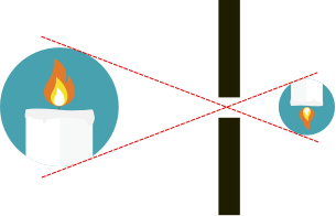
我们忽略光线所具有的“波”的性质。我们仅需知道,“光是沿直线传播的”。那么,如图 2所示物体上发出的光只能经过小孔落在成像平面上。经过小孔,上方的光线落在下面,下方的光线落在上面。小孔成像所成的是倒立的实像。
虽然小孔成像在物理上是这样解释的,但是,计算机从业者却常用另外的图示来表达这一过程。

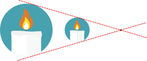
在图 3中,你可以看到对象物体和所成像都画在小孔(又被称为主点)的同一侧,并且直接绘制正像。你可能会问,这种事在物理上怎么可能发生呢?
这在物理上当然是不合理的。之所以计算机的从业者这样绘图,只是因为方便。这种画法因为能节省作图空间,且避免了麻烦的坐标系旋转而十分常见。通过避免坐标旋转,可以简化数学运算。
小孔成像的原理可以很容易用数学公式描述。假设相机坐标系中有一点\(\mathbf p_c=(x_c, y_c, z_c)^T\),这个点发出的光线经过了小孔,那么可以通过如下公式求得成像点的位置:
\[ x = \frac{x_c f}{z_c}, y = \frac{y_c f}{z_c}.\]
其中\(f\)是小孔到成像平面的距离。 图 4或许有助于你理解该公式。从图中我们可以看到,成像点总是位于\(z = f\)的平面上,并且与原点\(\mathbf o\)和被成像点\(\mathbf p_c\)共线。因此,我们只须求出直线\(\mathbf o \mathbf p_c\)与成像平面的角点,也就得到了成像点的坐标。
在计算机视觉应用中,图像会被离散化为以像素为单位的矩阵。要将\(x\)和\(y\)坐标同像素的行列对应起来,还需要在成像公式中加入缩放系数和偏移量:
\[ c = \frac{x_c f}{z_c s_x} + c_x, r = \frac{y_c f}{z_c s_y} + c_y. \]
这里\(s_x\)和\(s_y\)就是感光芯片阵列在横向和纵向上的间距。 这样,通过这个公式,我们就知道点\(\mathbf p_c\)落在图像\(r\)行\(c\)列的位置。
令\(f_x = f / s_x\),以及\(f_y = f / s_y\),则有
\[ c = \frac{x_c f_x}{z_c} + c_x, r = \frac{y_c f_y}{z_c} + c_y.\]
对于市面上的相机,一般都有\(s_x=s_y\),于是\(f_x = f_y\)。一种\(s_x\neq s_y\)的特殊情况(见文献[1] 71页的2.3.1节),是采集卡的时钟频率与摄像机时钟频率不一致从而导致像素横纵比率改变。这种情形比较少见。
这两个公式可以转写为方便的矩阵乘法的形式: \[ (c',r', z_c)^T = \left( \begin{array}{ccc} f_x & 0 & c_x\\ 0 & f_y & c_y\\ 0 & 0 & 1 \end{array} \right) \left( \begin{array}{c} x_c\\ y_c\\ z_c \\ \end{array} \right) = \mathbf P \left( \begin{array}{c} x_c\\ y_c\\ z_c \\ \end{array} \right) \] 其中\(\mathbf P\)被称为投影矩阵,\(c'\)、\(r'\)是横纵坐标的分子,而\(z_c\)是它们公共的分母: \[ c = \frac{c'}{z_c} \]
\[ r = \frac{r'}{z_c} \]
结合内参和外参,则成像点的计算公式是: \[ s\left( \begin{array}{c} c\\r\\1 \end{array} \right) = \mathbf P(\mathbf R\mathbf p_w + \mathbf T) = \mathbf P (\mathbf r_1, \mathbf r_2, \mathbf r_3, \mathbf t) \left( \begin{array}{c} x_w\\ y_w\\ z_w\\ 1 \end{array} \right) \tag{1}\] 其中\(r_i\)是矩阵\(\mathbf R\)的第i列。
3.2 镜头畸变
对于大多数镜头而言,它们的畸变都可以被近似为径向畸变。

径向畸变: \[ \left( \begin{array}{c} u' \\ v' \end{array} \right) = \frac{2}{1 + \sqrt{1 - 4 \kappa (u^2 + v^2)}} \left( \begin{array}{c} u \\ v \end{array} \right) \]
这是Halcon库采用的畸变公式。不同的程序库或文献可能使用不同的畸变公式。例如,OpenCV有一套更复杂的畸变描述方式。 它们的共同特征是用非线性函数来表示畸变。
昂贵的工业相机可以使用简单的畸变模型,而便宜的网络相机可能需要使用复杂的畸变模型。
4 标定
标定就是求解相机内外参的过程。对于针孔相机模型,我们有内参数\((\kappa, f_x, f_y, c_x, c_y)\),外参数\((\alpha, \beta, \gamma, t_x, t_y, t_z)\). 标定时我们需要拍摄多张标定板的图像。虽然相机的内参是固定的,但每次拍摄,标定板的位置都不一样,所以每次拍摄都产生一组待解的外参。总的待解参数的量是\(\text{内参数量}+\text{外参数量}\times\text{图片数量}\).
4.1 标定工具
我们使用张氏标定法来完成标定。需要使用标定板这一工具

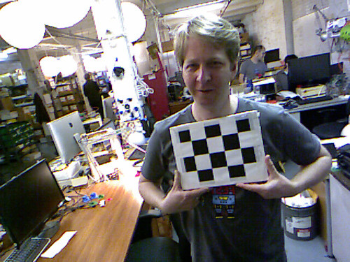
标定板是黑白相间的方格子,这种被称为“棋盘格标定板”。材质有A4纸的、铝合金的,也有玻璃制的。材质决定了标定板的精度,也影响标定精度。如果你的应用场景对标定精度的要求很高,你可能需要选择一种昂贵的材料,而不是简单地用A4纸打印一张标定板。
我们检测的是棋盘格标定板上的角点。角点的个数最好是奇数个x偶数个。图案最好不是旋转对称的。
也有圆形图案的标定板。但我更喜欢棋盘格图案,因为圆形的投影中心不一定是圆形的中心,这会给检测带来麻烦。另外,角点检测也比边缘检测准确,后者容易受光照影响而发生偏移。椭圆拟合的准确性依赖于边缘检测,因此拍照时必须控制好光照。
4.2 标定流程
标定时,我们从多个方位拍摄标定板,产生若干图像(例如15张,30张)。
拍好照片后,可以使用广为人知、影响深远的张氏标定法[2]求解相机内外参。
4.3 内外参的闭式解
先从简单的情况著手——假设不存在畸变,此时问题有闭式解。
我们需要做的只是求解线性变换:
\[ s\left( \begin{array}{c} c\\r\\1 \end{array} \right) = \mathbf P(\mathbf R\mathbf p_w + \mathbf T) = P (\mathbf r_1, \mathbf r_2, \mathbf r_3, \mathbf t) \left( \begin{array}{c} x_w\\ y_w\\ z_w\\ 1 \end{array} \right) \]
注意标定板是平面,所以\(z_w = 0\),上式化简为
\[ s\left( \begin{array}{c} c\\r\\1 \end{array} \right) = \mathbf P(\mathbf R\mathbf p_w + \mathbf T) = \mathbf P (\mathbf r_1, \mathbf r_2, \mathbf t) \left( \begin{array}{c} x_w\\ y_w\\ 1 \end{array} \right) \]
令\(\mathbf H = \mathbf P(\mathbf r_1, \mathbf r_2 , \mathbf t)\),上式可以写为 \[\tilde{\mathbf m} = \mathbf H \tilde{\mathbf M}\] 其中\(\tilde{\mathbf m}\)表示点在图像上的投影的齐次坐标,\(\tilde{\mathbf M}\)表示点在标定板上的坐标。 只要标定板上的点足够多,那么就可以用最小二乘法求得\(\mathbf H\).
又令\(\mathbf H = \left[\mathbf h_1, \mathbf h_2, \mathbf h_3\right]\),其中\(\mathbf h_i\)是其第i列的三维向量。
由于R是单位正交阵,所以\(r_1\), \(r_2\)是相互正交的单位向量,故而 \[ \mathbf h_1^T \mathbf P^{-T} \mathbf P^{-1} \mathbf h_2 = 0 \tag{2}\]
\[ \mathbf h_1^T \mathbf P^{-T} \mathbf P^{-1} \mathbf h_1 = \mathbf h_2^T \mathbf P^{-T} \mathbf P^{-1} \mathbf h_2 \tag{3}\]
再令 \[\mathbf B = \lambda \mathbf P^{-T} \mathbf P^{-1} \equiv \left( \begin{array}{ccc} B_{11} & B_{12} & B_{13} \\ B_{12} & B_{22} & B_{23} \\ B_{13} & B_{23} & B_{33} \\ \end{array}\right) \] 其中\(\lambda\)是一个任意的缩放系数。\(\mathbf B\)是一个对称矩阵。注意到由于本文对\(\mathbf P\)的定义,\(B_{12}=0\). 所以\(\mathbf B\)可以由六维向量\(\mathbf b = \left(B_{11}, B_{22}, B_{13}, B_{23}, B_{33}\right)^T\)决定。
设\(\mathbf h_i = (h_{i1}, h_{i2}, h_{i3})^T\)是\(\mathbf H\)的第i列,那么, \[ \mathbf h_i^T \mathbf{B} \mathbf h_j = \mathbf v_{ij}^T \mathbf b, \] 其中 \[ \mathbf v_{ij} = (h_{i1}h_{j1}, h_{i2}h_{j2}, h_{i3}h_{j1} + h_{i1} h _{j3}, h_{i3}h_{j2} + h_{i2}h_{j3}, h_{i3}h_{j3}) \] 于是,公式 2、公式 3中的约束可以转化为如下线性约束: \[ \left(\begin{array}{c} \mathbf v_{12}^T \\ (\mathbf v_{11} - \mathbf v_{12}) ^T \end{array} \right) \mathbf b = \mathbf 0 \]
假设我们拍摄了n张图片,那么将n个这样的公式堆叠起来,就得到 \[ \mathbf V \mathbf b = \mathbf 0 \]
\(\mathbf V\)是由\(\mathbf H\)决定的,可以通过单张图像求得,而\(\mathbf b\)是由相机的内参决定的。我们要求得\(\mathbf b\)。可以用著名的线性最小二乘法求解这个问题。只要数据点足够多,则这个问题有闭式解。
一旦\(\mathbf b\)得解,那么我们可以恢复出相机的内参。可以证明 \[ \begin{aligned} c_y &= - B_{11} B_{23} / (B_{11}B_{22}) \\ \lambda &= B_{33} - (B_{13}^2 + c_y (- B_{11}B_{23})) / B_{11} \\ f_x &= \sqrt{\lambda / B_{11}} \\ f_y &= \sqrt{\lambda B_{11} / (B_{11}B_{22})} \\ c_x &= - B_{13} \alpha^2 / \lambda \end{aligned} \]
接下来,各张图像的外参也可依次求得。 \[ \mathbf r_1 = \lambda \mathbf A^{-1}\mathbf h_1, \mathbf r_2 = \lambda \mathbf A^{-1} \mathbf h_2 , \mathbf r_3 = \mathbf r_1 \times \mathbf r_2, \mathbf t = \lambda \mathbf A ^{-1} \mathbf h_3\] 注意,这里求解出的旋转矩阵可能不是单位正交矩阵,需要用SVD分解的方法将其转变为单位正交阵。
总结一下本小节的内容:假设相机没有畸变,那么可以先求得每张图像对应的单应性变换矩阵\(\mathbf H\),然后,可以依次求得相机内外参。这种情况下,内外参数的解是闭式解。
4.4 求相机的畸变系数
上一节,我们求解了相机的内外参。但这种解法存在几个问题:
- 我们假设相机没有畸变;
- 我们通过最小二乘来求解问题。但这里应用的最小二乘所最小化的距离度量没有实际的物理意义。
所以,张氏标定法用上一节所介绍的方法求得的解作为初始解,用LM算法继续优化该解。目标函数为: \[\sum_{i} \sum_{j} \left\| m_{ij} - \phi(\mathbf P, \mathbf R_i \mathbf t_i, \mathbf M_j)\right\| ^2\] 其中\(\phi\)是考虑了相机畸变的非线性投影函数,解决了问题 1. 新的目标函数旨在最小化投影误差,是具有实际物理意义的,解决了问题2.
5 思考题
一张标定板最少应该有多少个点?至少应当拍摄多少张标定板图像?
标定板的点数至少应该使得\(H\)可解。而三维方阵\(H\)作为单应性变换,有8个自由度。 标定板的每个点都可以提供两行投影方程,因此如果有四个点,则理论上\(H\)可解。因为\(\mathbf V\)是\(2n\)行的矩阵,而内参(不包括畸变系数,分别是\(f_x\)、\(f_y\)、\(c_x\)、\(c_y\))有4个,故而理论上图片张数\(n\geq 2\)时问题可解。
当然,实际上为了获得较好的精度,我们会适当取多一些点,多几张图片。实践中,如果点数、图片数不够多,解的精度是很差的。
6 参考文献
7 附录
7.1 标定算法的Python实现
OpenCV/Halcon等库提供了标定用的函数,可以非常方便的用Python或者C++调用。尽管如此,不同的程序库使用的相机模型有略微的差别。只有真正了解相机模型,理解每一个参数,才能正确地使用它们。
参考Halcon的资料[1] ,我用Python实现了一份标定算法。经测试,标定结果同Halcon的标定算法所产生的结果一致(误差小于0.01)。这份代码对于理解Halcon的相机模型、标定原理可能有帮助,仅供参考。
展开代码
# -*- coding: utf-8 -*-

import numpy as np
import cv2 as cv

sin, cos = np.sin, np.cos


# 旋转矩阵分解为欧拉角
# 该函数只能得到其中一种特解
# 参考:https://www.geometrictools.com/Documentation/EulerAngles.pdf
def rotate_matrix_factorize(mat):
    assert(mat.shape == (3, 3))
    eps = np.finfo(mat.dtype).eps
    r00, r01, r02, r10, r11, r12, r20, r21, r22 = mat.flatten()
    if np.abs(r02 - 1) < eps:
        # 标定板正好垂直于成像平面,
        # 分解方式不唯一,
        # 随便返回一个特解算了
        return 0, np.pi / 2, np.arctan2(r10, r11)
        # TODO: 把这种标定板剔除掉比较好
    elif np.abs(r01 + 1) < eps:
        # 如同上一种情况
        return 0, -np.pi / 2, np.arctan2(r10, r11)
    else:
        return np.arctan2(-r12, r22), np.arcsin(r02), np.arctan2(-r01, r00)


# 由投影变换矩阵和内参估计外参
def estimate_outer_params(cx, cy, fx, fy, mat_h):
    # 内参矩阵
    mat_m = np.matrix([[fx,  0,  cx],
                       [0,   fy, cy],
                       [0,   0,  1]])
    lamb = 1 / np.linalg.norm(np.matmul(mat_m.I, mat_h[:, 0]))
    # 旋转矩阵
    r1 = lamb * np.matmul(mat_m.I, mat_h[:, 0])
    r2 = lamb * np.matmul(mat_m.I, mat_h[:, 1])
    r3 = np.cross(r1, r2)
    mat_r = np.array([r1, r2, r3]).reshape((3, 3)).T
    # 旋转矩阵要强制转化为正交的
    u, s, vh = np.linalg.svd(mat_r)
    mat_r = np.matmul(np.matmul(u, np.eye(3, 3)), vh)
    # 从旋转矩阵取旋转角度
    alpha, beta, gamma = rotate_matrix_factorize(mat_r)
    # 位移向量
    t = np.array(lamb * np.matmul(mat_m.I, mat_h[:, 2].reshape(3, 1)))
    return alpha, beta, gamma, t


def predict1(points, cx, cy, sx, sy, f, kappa, outer_params):
    scene_num = outer_params.shape[0]
    pt_num = points.shape[0]
    assert(outer_params.shape == (scene_num, 6))
    assert(points.shape == (pt_num, 2))
    points_transpose = points.T  # shape: (2, pt_num)
    points_camera = np.empty((3, pt_num * scene_num))

    # 变换到相机坐标系
    for i in range(scene_num):
        alpha, beta, gamma, tx, ty, tz = outer_params[i]

        # 绕z轴旋转。
        points_rotate_z = np.matmul([
            [np.cos(gamma), -np.sin(gamma)],
            [np.sin(gamma), np.cos(gamma)]
        ],
            points_transpose)
        assert(points_rotate_z.shape == (2, pt_num))

        # 绕y轴旋转
        points_rotate_y = np.matmul([
            [np.cos(beta), 0],
            [0, 1],
            [-np.sin(beta), 0]
        ],
            points_rotate_z)
        assert(points_rotate_y.shape == (3, pt_num))

        # 绕x轴旋转
        points_rotate_x = np.matmul([
            [1, 0, 0],
            [0, np.cos(alpha), -np.sin(alpha)],
            [0, np.sin(alpha), np.cos(alpha)]
        ], points_rotate_y)

        # 平移到相机坐标系
        points_camera[:, i * pt_num: (i + 1) * pt_num] = points_rotate_x + [[tx], [ty], [tz]]

    # 投影到成像平面
    points_image_plane = points_camera[:2, :] / points_camera[2, :] * f
    assert(points_image_plane.shape == (2, pt_num * scene_num))

    # 畸变
    r2 = np.sum(np.power(points_image_plane, 2), axis=0)
    assert(r2.shape == (pt_num * scene_num,))
    ratio = 2 / (1 + np.sqrt(1 - 4 * kappa * r2))
    points_distort = ratio * points_image_plane
    assert(points_distort.shape == (2, pt_num * scene_num))
    r2d = np.sum(np.power(points_distort, 2), axis=0)
    assert(r2d.shape == (pt_num * scene_num,))

    # 到图像坐标系
    points_image = [[1 / sx], [1 / sy]] * points_distort + [[cx], [cy]]
    assert(points_image.shape == (2, pt_num * scene_num))

    # 雅可比矩阵,左起5列对应内参cx, cy, sx, f, kappa,往右每6列对应一组外参
    # 上半部分对应标定点的横坐标,下半部分对应纵坐标
    jac = np.empty((2 * pt_num * scene_num, 5 + scene_num * 6))

    # 横坐标对cx的偏导数
    jac[:pt_num * scene_num, 0] = 1
    # 纵坐标对cx的偏导数
    jac[pt_num * scene_num:, 0] = 0


    # 对cy的偏导数
    jac[:pt_num * scene_num, 1] = 0
    jac[pt_num * scene_num:, 1] = 1

    # 对sx的偏导数
    jac[:pt_num * scene_num, 2] = -points_distort[0, :] / sx ** 2
    jac[pt_num * scene_num:, 2] = 0

    # 对f求偏导数
    d_ud_u = 2 * kappa * points_distort[0, :] ** 2 / np.sqrt(1 - 4 * kappa * r2) + ratio
    d_ud_v = 2 * kappa * points_image_plane[0, :] * points_distort[1, :] ** 2 / points_image_plane[1, :] / np.sqrt(1 - 4 * kappa * r2)
    d_vd_u = d_ud_v
    d_vd_v = 2 * kappa * points_distort[1, :] ** 2 / np.sqrt(1 - 4 * kappa * r2) + ratio

    jac[:pt_num * scene_num, 3] = (1 / sx * (d_ud_u * points_camera[0, :] / points_camera[2, :]
                                            + d_ud_v * points_camera[1, :] / points_camera[2, :])).flatten()
    jac[pt_num * scene_num:, 3] = (1 / sy * (d_vd_u * points_camera[0, :] / points_camera[2, :]
                                            + d_vd_v * points_camera[1, :] / points_camera[2, :])).flatten()

    # 对kappa的偏导数
    jac[:pt_num * scene_num, 4] = (1 / sx * points_image_plane[0] / np.sqrt(1 - 4 * kappa * r2) * r2d).flatten()
    jac[pt_num * scene_num:, 4] = (1 / sy * points_image_plane[1] / np.sqrt(1 - 4 * kappa * r2) * r2d).flatten()

    # 对外参求偏导数
    # shape: (pt_num * scene_num,)
    d_c_xc = 1 / sx * d_ud_u * f / points_camera[2, :]
    d_c_yc = 1 / sx * d_ud_v * f / points_camera[2, :]
    d_c_zc = -1 / sx * (d_ud_u * f * points_camera[0, :] / points_camera[2, :] ** 2
                        + d_ud_v * f * points_camera[1, :] / points_camera[2, :] ** 2)
    d_r_xc = 1 / sy * d_vd_u * f / points_camera[2, :]
    d_r_yc = 1 / sy * d_vd_v * f / points_camera[2, :]
    d_r_zc = -1 / sy * (d_vd_u * f * points_camera[0, :] / points_camera[2, :] ** 2
                        + d_vd_v * f * points_camera[1, :] / points_camera[2, :] ** 2)
    for scene in range(scene_num):
        d_c_xc_slice = d_c_xc[scene * pt_num:(scene + 1) * pt_num]
        d_c_yc_slice = d_c_yc[scene * pt_num:(scene + 1) * pt_num]
        d_c_zc_slice = d_c_zc[scene * pt_num:(scene + 1) * pt_num]
        d_r_xc_slice = d_r_xc[scene * pt_num:(scene + 1) * pt_num]
        d_r_yc_slice = d_r_yc[scene * pt_num:(scene + 1) * pt_num]
        d_r_zc_slice = d_r_zc[scene * pt_num:(scene + 1) * pt_num]
        jac_slice1 = jac[scene * pt_num:(scene + 1) * pt_num, :]
        jac_slice2 = jac[(scene_num + scene) * pt_num:(scene_num + scene + 1) * pt_num, :]
        alpha, beta, gamma, _, _, _ = outer_params[scene]

        #  xc = [cos(beta) * cos(gamma) * x - cos(beta) * sin(gamma) * y],
        #  yc = [x * (cos(alpha) * sin(gamma) + cos(gamma) * sin(alpha) * sin(beta))
        #      + y * (cos(alpha) * cos(gamma) - sin(alpha) * sin(beta) * sin(gamma))],
        #  zc = [x * (-cos(alpha) * cos(gamma) * sin(beta) + sin(alpha) * sin(gamma))
        #      + y * (cos(alpha) * sin(beta) * sin(gamma) + cos(gamma) * sin(alpha))]

        d_xc_alpha = 0
        d_xc_beta = -sin(beta) * cos(gamma) * points_transpose[0, :] \
            + sin(beta) * sin(gamma) * points_transpose[1, :]
        d_xc_gamma = -cos(beta) * sin(gamma) * points_transpose[0, :] \
            - cos(beta) * cos(gamma) * points_transpose[1, :]
        d_yc_alpha = points_transpose[0, :] * (-sin(alpha) * sin(gamma) + cos(gamma) * cos(alpha) * sin(beta)) \
            + points_transpose[1, :] * (-sin(alpha) * cos(gamma) - cos(alpha) * sin(beta) * sin(gamma))
        d_yc_beta = points_transpose[0, :] * cos(gamma) * sin(alpha) * cos(beta) \
            - points_transpose[1, :] * sin(alpha) * cos(beta) * sin(gamma)
        d_yc_gamma = points_transpose[0, :] * (cos(alpha) * cos(gamma) - sin(gamma) * sin(alpha) * sin(beta)) \
            + points_transpose[1, :] * (-cos(alpha) * sin(gamma) - sin(alpha) * sin(beta) * cos(gamma))
        d_zc_alpha = points_transpose[0, :] * (sin(alpha) * cos(gamma) * sin(beta) + cos(alpha) * sin(gamma)) \
            + points_transpose[1, :] * (-sin(alpha) * sin(beta) * sin(gamma) + cos(gamma) * cos(alpha))
        d_zc_beta = points_transpose[0, :] * -cos(alpha) * cos(gamma) * cos(beta) \
            + points_transpose[1, :] * cos(alpha) * cos(beta) * sin(gamma)
        d_zc_gamma = points_transpose[0, :] * (cos(alpha) * sin(gamma) * sin(beta) + sin(alpha) * cos(gamma)) \
            + points_transpose[1, :] * (cos(alpha) * sin(beta) * cos(gamma) - sin(gamma) * sin(alpha))
        # alpha
        jac_slice1[:, 5 + scene * 6] = d_c_xc_slice * d_xc_alpha + d_c_yc_slice * d_yc_alpha + d_c_zc_slice * d_zc_alpha
        jac_slice2[:, 5 + scene * 6] = d_r_xc_slice * d_xc_alpha + d_r_yc_slice * d_yc_alpha + d_r_zc_slice * d_zc_alpha

        # beta
        jac_slice1[:, 6 + scene * 6] = d_c_xc_slice * d_xc_beta + d_c_yc_slice * d_yc_beta + d_c_zc_slice * d_zc_beta
        jac_slice2[:, 6 + scene * 6] = d_r_xc_slice * d_xc_beta + d_r_yc_slice * d_yc_beta + d_r_zc_slice * d_zc_beta

        # gamma
        jac_slice1[:, 7 + scene * 6] = d_c_xc_slice * d_xc_gamma + d_c_yc_slice * d_yc_gamma + d_c_zc_slice * d_zc_gamma
        jac_slice2[:, 7 + scene * 6] = d_r_xc_slice * d_xc_gamma + d_r_yc_slice * d_yc_gamma + d_r_zc_slice * d_zc_gamma

        # tx
        jac_slice1[:, 8 + scene * 6] = d_c_xc_slice
        jac_slice2[:, 8 + scene * 6] = d_r_xc_slice

        # ty
        jac_slice1[:, 9 + scene * 6] = d_c_yc_slice
        jac_slice2[:, 9 + scene * 6] = d_r_yc_slice

        # tz
        jac_slice1[:, 10 + scene * 6] = d_c_zc_slice
        jac_slice2[:, 10 + scene * 6] = d_r_zc_slice
    return points_image, jac


def calibrate(grids, params):
    pattern_size = params['pattern size']
    cell_width = params['cell width']
    image_count = grids.shape[0]

    # 随机显示一张标定板检测结果
    # import random
    # show_grid(pattern_size, imgs, grids, random.randint(0, len(imgs) - 1))

    # 计算世界坐标系中的标定板坐标
    grid_x = (np.arange(pattern_size[0] * pattern_size[1]) % pattern_size[0]) * cell_width
    grid_y = np.asarray(np.arange(pattern_size[0] * pattern_size[1]) / pattern_size[0], np.int) * cell_width
    grid_world = np.empty((pattern_size[0] * pattern_size[1], 2))
    grid_world[:, 0] = grid_x
    grid_world[:, 1] = grid_y

    # 提取内参初始值
    obj_points = np.float32(np.tile(np.hstack((grid_world, np.zeros((grid_world.shape[0], 1)))), (image_count, 1)))\
        .reshape(image_count, pattern_size[0] * pattern_size[1], 3)
    camera_matrix = np.array(cv.initCameraMatrix2D(
        obj_points,
        np.float32(grids),
        (1280, 1024)
    ))
    fx, _, cx, _, fy, cy, _, _, _ = camera_matrix.flatten()
    sy = 4.8e-3
    f = fy * sy
    sx = f / fx
    kappa = 0
    outer_params = np.empty((image_count, 6))
    for i in range(image_count):
        mat_h, _ = cv.findHomography(obj_points[i], grids[i])
        alpha, beta, gamma, t = estimate_outer_params(cx, cy, f / sx, f / sy, mat_h)
        outer_params[i, :] = [alpha, beta, gamma, t[0], t[1], t[2]]

    lamb = 100
    g1 = 0.1
    g2 = 1.1
    i1 = 1e-1
    i2 = 0.99
    mat_i = np.eye(5 + 6 * image_count)
    for i in range(100):
        points_predict, jac = predict1(grid_world, cx, cy, sx, sy, f, kappa, outer_params)
        assert(points_predict.shape == (2, pattern_size[0] * pattern_size[1] * image_count))
        delta = points_predict - grids.reshape(pattern_size[0] * pattern_size[1] * image_count, 2).T
        assert(delta.shape == (2, pattern_size[0] * pattern_size[1] * image_count))
        error = np.mean(np.sum(delta ** 2, axis=0))
        print('平均误差:', np.sqrt(error))

        # 更新内外参
        mat_a = np.matmul(jac.T, jac)
        step = -np.matmul(np.mat(mat_a + lamb * mat_i).I,
                          np.matmul(jac.T, delta.reshape(pattern_size[0] * pattern_size[1] * image_count * 2, 1)))
        assert(step.size == 5 + 6 * outer_params.shape[0])
        step = np.array(step).flatten()
        cx, cy, sx, f, kappa = np.array([cx, cy, sx, f, kappa]) + step[:5]
        outer_params += step[5:].reshape(outer_params.shape[0], 6)

        # 更新LM算法的参数
        points_predict2, _ = predict1(grid_world, cx, cy, sx, sy, f, kappa, outer_params)
        delta2 = points_predict2 - grids.reshape(pattern_size[0] * pattern_size[1] * image_count, 2).T
        error2 = np.mean(np.sum(delta2 ** 2, axis=0))
        points_predict3 = points_predict + np.matmul(jac, step.reshape(5 + 6 * image_count, 1)) \
            .reshape(2, pattern_size[0] * pattern_size[0] * image_count)
        delta3 = points_predict3 - grids.reshape(pattern_size[0] * pattern_size[1] * image_count, 2).T
        error3 = np.mean(np.sum(delta3 ** 2, axis=0))
        p = (error - error2) / (error - error3)
        lamb = g2 * lamb if p < i1 else \
            lamb if i1 <= p < i2 else\
            g1 * lamb

    print(
        '''用LM法优化得到:
            cx: %f px;
            cy: %f px;
            sx: %f um;
            sy: %f um;
            f: %f mm;
            kappa: %f 1/m^2;
        ''' % (cx, cy, sx * 1e3, sy * 1e3, f, kappa * 1e6)
    )


def main():
    # 初始参数
    # 实际距离全部以毫米为单位
    params = {
        'pattern size': (7, 7),  # 标记圆的个数
        'cell width': 25,  # 标记点间距
        'sx': 4.8e-3,
        "sy": 4.8e-3
    }
    pattern_size = params['pattern size']

    # 列出文件夹下的所有图片
    directory = './test_images_1'
    files = []

    import sys
    import os
    for file in os.listdir(directory):
        path = os.path.join(directory, file)
        if os.path.isfile(path) and path.endswith('.bmp'):
            files.append(path)
    if len(files) < 2:
        print("至少需要两份标定文件!", sys.stderr)
        # exit(128)

    # 读取图片
    imgs = []
    for file in files:
        imgs.append(cv.imread(file, cv.IMREAD_GRAYSCALE))

    # 检测圆点
    grids = np.zeros((len(imgs), params['pattern size'][0] * params['pattern size'][1], 2))

    # 有两种方法可以读取坐标:
    # 1. 直接从halcon的识别结果中读取坐标(halcon的检测结果更准);
    # 2. 或者调用opencv的检测算法读取坐标。
    # 注释掉你不用的那个方法。

    '''
    # 直接取halcon识别结果
    for i, file in enumerate(files):
        with open(file + '.d', 'r') as file_halcon_result:
            lines = file_halcon_result.readlines()
            for j, line in enumerate(lines):
                coord = line.strip().split(' ')
                if len(coord) != 2:
                    continue
                grids[i, j, 0] = float(coord[0])
                grids[i, j, 1] = float(coord[1])
    '''

    # 从图片提取圆点
    for i, img in enumerate(imgs):
        success, centers = cv.findCirclesGrid(img, pattern_size)
        if not success:
            return {
                'success': False,
                'msg': '标定板无法识别',
                'error code 1': 123,
                'error code 2': i
            }
        assert(centers.shape == (pattern_size[0] * pattern_size[1], 1, 2))
        grids[i, :, :] = centers.reshape(pattern_size[0] * pattern_size[1], 2)
    calibrate(grids, params)


if __name__ == '__main__':
    main()
7.2 版权信息
图像: